April is a slow month for me, but my father has been busy, so a word from him;
Water Jet Powered Boat
So being into model boats I started looking for something to make with my new 3D printer.
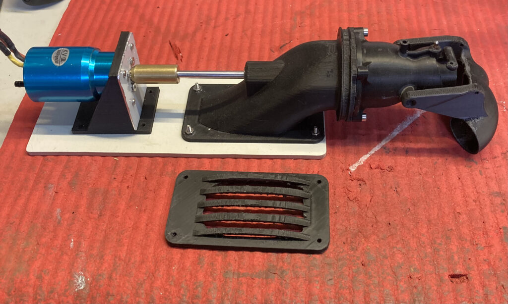
I found a water jet that showed promise so I set about printing it.
I tried various different orientations of the parts on the print bed to get the best detail on parts with mating surfaces or bearing recesses.
I built a working prototype to iron out any wrinkles, and there was quite a few.
First problem, how to attach the impeller to the shaft, I used a 5mm stainless steel shaft which needed to protrude 8mm through the impeller, to enter a sealed roller bearing, and the impeller itself is 16mm.
What I did was grind 2 flats on the shaft where the impeller was going to be then I put the shaft in the drill press, heated the shaft with a small gas torch and simply pressed the shaft into the correct place, lifted it with the impeller fixed and lowered it into a cup of water to cool it and that was it.
I mounted the motor so that the shafts were in line and turned a solid connector to join them. The problem with this arrangement is that all the thrust is taken by the motor bearings, that’ll be okay for the trial but I’m working on an upgrade by using a tube on the shaft secured into the inlet that will take the thrust.
At this point I’d already built a second jet and put it into a boat. I had some trouble with a leak because I had trouble finding the correct size ‘o’ring, I sealed this with silicone for the lake trial.
I’ve fitted an Action Electronics P105 to operate the reverse bucket servo and fitted a servo to move the jet nozzle for steering, all I’ve got to do now is sort out a 2 channel radio and it’ll get tested hopefully in a few days.
The designer used a 2045kv with a 3s lipo which produced a no load rpm of 22,700.
I used a motor I had in my spares box, 3600kv with a 2s lipo which produces 26,640 no load rpm.
The day before the lake trial I was examining some of the components, the impeller is built to drive anti-clockwise and the stator is for a clockwise turning impeller, this will work but the performance will be compromised.
When the impeller is pushing water it is also spinning it, the stator has fins inside to straighten out the thrust to reach its full potential.
It was too late to correct that so the lake trial went ahead knowing it was likely to be underpowered.
I printed out some new components using the mirror function on the printer to change the orientation of the impeller and stator for future trials.
Well the day of the lake trial came, it was a very windy day which proved that the steering needed more movement to be effective.
The drive was very smooth with a reasonable turn of speed but it was clear further work was needed on the steering.
Trials were fairly successful but steering was poor, not helped by a strong wind.
It’s now back on the bench with a new inlet which includes an outer tube on the impeller shaft instead of a ball race which doubles as a water seal and thrust bearing.
A redesigned stator which will be more effective in straightening the jet to increase thrust .
After that it’s make it steer better, I’ve got a couple of ideas.